Mô tả
Em4305 FDX-B 134.2khz RFID Micro Chip
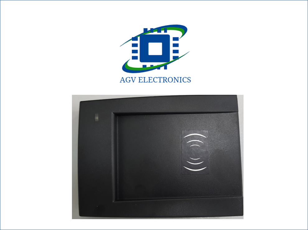
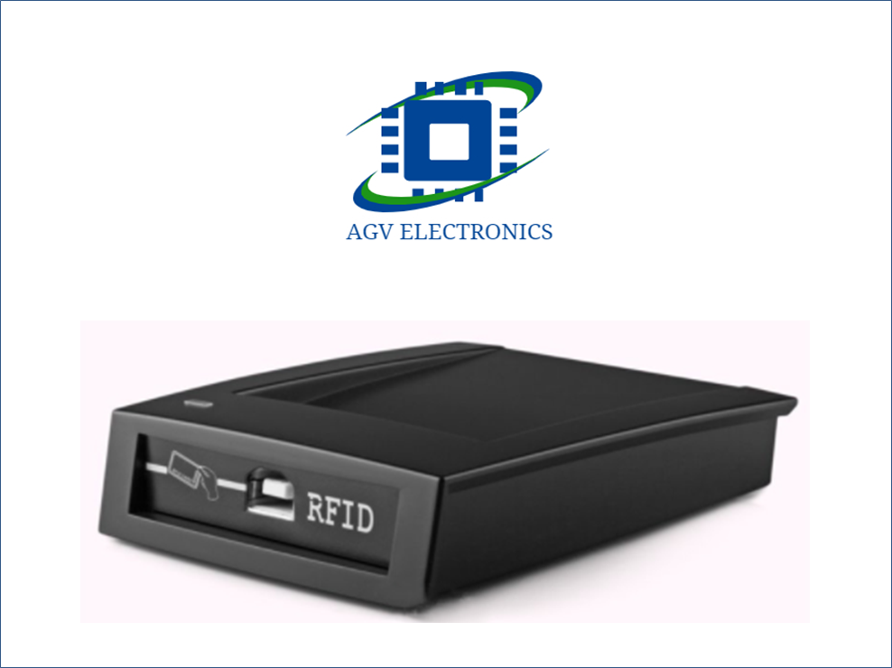
T5577 & EM4305 two-in-one desktop reader is a member of our company’s low frequency 134.2khz/ 125K (Low Frequency) RFID. The reader circuit and read-write algorithm have been carefully optimized. It has the characteristics of low power consumption, sensitive induction, stable card reading and fast card reading.
With this reader software program, it can be used to copy ID (EM4100) card, EM4100,T5577,Em4305 card, and so on. Animal label (ISO11784/85) and S256 cards can automatically produce ID (EM4100), animal label (ISO11784/85) and S256 cards continuously. With the API interface program provided by this reader, the reader can be quickly integrated into various card issuing, checking in and charging systems.
|
Item |
Parameters |
|
Model |
HC-FX-134 |
|
Frequency |
125Khz & 134.2Khz |
|
Support cards |
H-itag-s2048/T5557/ATA5567/ATA5577/EM4305/ etc |
|
Size |
110mm×80mm×26mm |
|
Colour |
Black |
|
Interface |
Virtual serial port(USB to RS232) |
|
Power Supply |
DC 5V |
|
Operating Distance |
0mm-50mm(related to the card or the environment) |
|
Service Temperature |
-10℃ ~ +70℃ |
|
Store Temperature |
-20℃ ~ +80℃ |
|
Working humidity |
<90% |
|
Read time |
<200ms |
|
Read interval |
<0.5S |
|
Weight |
About 140G |
|
Cable length |
1400mm |
|
Material of reader |
ABS |
|
Operating System |
Win XP\Win CE\Win 7\Win 10\LIUNX\Vista\Android |
|
Indicators |
Double Color LED (Red & Green) and Buzzer |
Reader and Writer Serial Port Protocol Technical Parameters overview
The external CPU is the main part, and the reader is the slave. The reader is always in the response state and does not actively send commands to the external CPU. 1 BIT start bit, 8 BIT data, 1 BIT stop bit.
Communication Protocol
1. External CPU command format
Command Header + Length Word + Command Word + Command Parameters + Check Bytes
Command Header: 2BYTES, 0xAADD
Length word: 2 BYTES, byte length from command word to check byte, high byte before, low byte after
Command word: 2 BYTES, high byte before, low byte after
Command parameters: can be null
Check bytes: 1 BYTE, byte-by-byte XOR from the command word to the last byte of the command parameter
Note: If there is a byte = AA from the length word to the check byte, the command header is distinguished by a byte 00, but the length word remains unchanged.
2. Reader Response Format
Command Header + Length Word + Command Word + Status Byte + Return Data + Check Byte
Command Header: 2BYTES, 0xAADD
Length word: 2 BYTES, byte length from command word to check byte, high byte before, low byte after
Command word: 2 BYTES, high byte before, low byte after
State bytes: 1 BYTE, 00 = success; non-zero = failure
Return data: can be empty
Check bytes: 1 BYTE, byte-by-byte XOR from the command word to the last byte of the returned data
Note: If there is a byte = AA from the length word to the check byte, the command header is distinguished by a byte 00, but the length word remains unchanged.
3. Examples (the following data are all in hexadecimal representations)
Send: AA DD 00 03 01 03 02
Return: AA DD 00 04 01 03 AA 00 A8
The following labeled “response data: “None” means that the “return data” part of the packet returned by the card reader is empty; when the command word sent is invalid, the next opportunity returns a packet with a status byte of 0x0A.
Setting Reader Command
1. Setting Baud Rate of Card Reader
Command code: 0x0101
Parameter: 01 = 9600
02=14400
03=19200
04=28800
05=38400
06=57600
07=115200
Note: The default baud rate of the card reader is 38400 after each power-on. If the baud rate of the card reader is modified, the baud rate of the host computer should also be modified after the execution of this instruction.
Response data: none
2. Get the type of card reader
Command code: 0x0102
Parameter: None
Note: When starting the host computer, the first step should be to send this command to see if the card reader is connected.
Response data: card reader model
3. beep
Command code: 0x0103
Parameter: 1 byte buzzing time, unit 5MS
Response data: none
4. Setting the color of LED
Command code: 0x0104
Parameter: 00 = extinguish
01 = red
02 = green
Note: The indicator light of the card reader is green and turns red after about 0.5S. At the same time, the buzzer beeps to indicate that the card reader starts successfully.
Response data: none
5. Sleeping Reader
Command code: 0x0105
Parameter: None
Note: When the reader receives this instruction, it first returns a confirmation message indicating that the reader has received the dormant instruction, and then the reader goes into the dormant state. After the reader is dormant, it will be in a low power state. Any instruction sent through the serial port can wake up the reader. This instruction can be used as a reset. Reader to use.
Response data: none
6. Read the FDX_B Microchip (ISO11784/85)
Command code: 0x010B
Parameter: None
Note: Each reader will have this function, so consider this command as setting the read and write command.
Response data: 12 BYTES card data, structured as follows:
5 BYTES Domestic Code + 2 BYTES National Code + 1 BYTE Data Logo + 1 BYTES Animal Logo + 3 BYTES Custom Data
7. Read em4100 card
Command code: 0x010C
Parameter: None
Note: Each reader will have this function, so consider this command as setting the read and write command.
Response data: 5 BYTES card data
ATA5567 Commend
In addition to card reading commands, other commands are all commands sent by card reader to the card. The return value of these functions only indicates that the process of sending data by card reader is completed. It does not mean that the command is correctly accepted by the card. For example, in the application program, there is usually a card reading command to determine whether the data is correct. Write in.
1. Write Cards
Command code: 0x0201
Parameters: 1 BYTE page address + 1 BYTE Lock + 4 BYTES data + 1 BYTE block address
Lock = 0x00 is not cured, Lock = 0x01 is cured.
Page address = 10 (binary) denotes page 0
Page address = 11 (binary) denotes page 1
Response data: none
2. Writing cards (with keys)
Command code: 0x0202
Parameters: 1 BYTE page address + 4 BYTES password + 1 BYTE Lock + 4 BYTES data + 1 BYTE block address
Lock = 0x00 is not cured, Lock = 0x01 is cured.
Page address = 10 (binary) denotes page 0
Page address = 11 (binary) denotes page 1
Note: When the card is encrypted, this command must be used to write the card.
Response data: none
3. Wake-up card
Command code: 0x0203
Parameter: 4 BYTES key
Note: When the card’s AOR bit is set to 0, the card will automatically send data to the reader. When the card’s AOR bit is set to 1, the card will not actively send data to the reader until it receives this command. This command can be used for anti-collision and the key is regarded as the address.
Response data: none
4. Visit cards
Command code: 0x0204
Parameter: 1 BYTE Page Address + 1 BYTE Block Address
Page address = 10 (binary) denotes page 0
Page address = 11 (binary) denotes page 1
Note: Set the data block of the specified address that the card returns automatically.
Response data: none
5. Access cards (with keys)
Command code: 0x0205
Parameters: 1 BYTE page address + 4 BYTES password + 1 BYTE block address
Page address = 10 (binary) denotes page 0
Page address = 11 (binary) denotes page 1
Note: If the card’s PWD bit is not set, this command will be mistaken for a card writing operation.
Response data: none
6. Select Storage Pages
Command code: 0x0206
Parameter: 1 BYTE page address
Page address = 10 (binary) denotes page 0
Page address = 11 (binary) denotes page 1
Note: ATA5567 totals two pages
Response data: none
7. Reset Card
Command code: 0x0207
Parameter: None
Note: Reset the card with Block 0 configuration
Response data: none
8. Manchester RF/32
Command code: 0x0208
Parameter: None
Note: The return data address is determined by the above 1-7 commands
Response data: 4*N (N = 1-7) bytes
9. Manchester RF/64
Command code: 0x0209
Parameter: None
Note: The return data address is determined by the above 1-7 commands
Response data: 4*N (N = 1-7) bytes
10. Format ATA5567 into S256 card
Command code: 0x020D
Parameters: 3 BYTES S256 Card Number
Response data: none
EM4305 Order
1. write cards
Command code: 0x0301
Parameter: 1 BYTE address + 4 BYTES data
Response data: none
2. reading card
Command code: 0x0302
Parameter: 1 BYTE address
Response data: 4 bytes
3. Verify passwords
Command code: 0x0303
Parameter: 4 BYTES key
Response data: none
4. Locking data blocks
Command code: 0x0304
Parameter: 4 BYTES Lock Word
Response data: none
5. Sleep Card
Command code: 0x0305
Parameter: None
Response data: none
6. Setting up the reading format of EM4305
Command code: 0x0306
Parameter: 1 byte
0x00 = Manchester RF/64
0x01 = Manchester RF/32
0x02 = Bi-phase RF/32
Note: EM4305 reader has three card formats: 1) Manchester RF/64; 2) Manchester RF/32; 3) Bi-phase RF/32. Manchester RF/64 corresponds to EM4100 card and Bi-phase RF/32 corresponds to FDX-B card. Reader power-on defaults to Manchester RF/64 card format, blank EM4305 format is Bi-phase RF/32.
Response data: none
Invalid Order
Command code: 0xXXXX
Parameters:
Note: When the reader receives an invalid command, the reader returns a packet with a status byte of 0x0A. An invalid command means that the command word is invalid, but the other data fields of the command must be correct.
Response data: none
CÔNG TY TNHH ĐIỆN TỬ PT AGV


Đánh giá
Chưa có đánh giá nào.